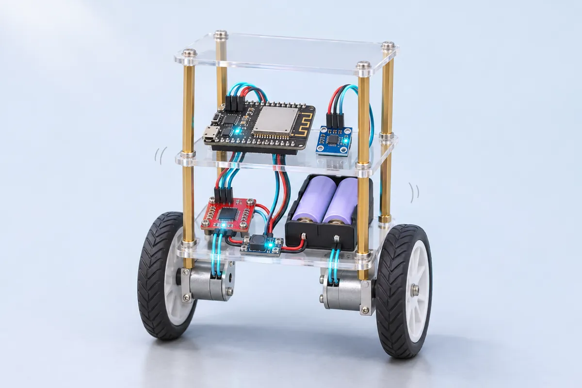
Parts list
| Part | Qty | Approx. | Buy |
|---|---|---|---|
| ESP32 DevKit V1 (30-pin) | 1 | ₹380 | Buy ESP32 DevKit V1 (30-pin) |
| MPU6050 (GY-521) gyro + accelerometer | 1 | ₹150 | Buy MPU6050 (GY-521) gyro + accelerometer |
| TB6612FNG dual motor driver | 1 | ₹180 | Buy TB6612FNG dual motor driver |
| 6 V metal gear motors (N20 or JGA25-370, 300–500 RPM) | 2 | ₹700 | Buy 6 V metal gear motors (N20 or JGA25-370, 300–500 RPM) |
| Wheels 65 mm with hubs for the motor shaft | 2 | ₹160 | Buy Wheels 65 mm with hubs for the motor shaft |
| 2× 18650 Li-ion cells + holder with switch (7.4 V) | 1 | ₹350 | Buy 2× 18650 Li-ion cells + holder with switch (7.4 V) |
| Mini 5 V buck converter (ESP32 supply from the pack) | 1 | ₹80 | Buy Mini 5 V buck converter (ESP32 supply from the pack) |
| Chassis: 3 acrylic or MDF decks + M3 standoffs (tall, 18–25 cm) | 1 | ₹250 | Buy Chassis: 3 acrylic or MDF decks + M3 standoffs (tall, 18–25 cm) |
| Total | ₹2,250 |
Affiliate disclosure: “Buy” links may earn FlashReady a small commission at no extra cost to you. Prices are indicative.
Wiring
| ESP32 DevKit V1 | Part · pin | Wire | Notes |
|---|---|---|---|
| — | TB6612FNG dual DC motor driver · A01 | — | To Left motor (+) (not drawn) |
| — | TB6612FNG dual DC motor driver · A02 | — | To Left motor (−) (not drawn) |
| — | TB6612FNG dual DC motor driver · B01 | — | To Right motor (+) (not drawn) |
| — | TB6612FNG dual DC motor driver · B02 | — | To Right motor (−) (not drawn) |
| D22 | MPU6050 (GY-521) · SCL | yellow | |
| D21 | MPU6050 (GY-521) · SDA | blue | |
| 3V3 | MPU6050 (GY-521) · VCC | red | |
| GND | MPU6050 (GY-521) · GND | black | |
| D25 | TB6612FNG dual DC motor driver · PWMA | orange | 20 kHz PWM, left motor speed |
| D26 | TB6612FNG dual DC motor driver · AIN1 | yellow | |
| D27 | TB6612FNG dual DC motor driver · AIN2 | green | |
| D32 | TB6612FNG dual DC motor driver · PWMB | purple | 20 kHz PWM, right motor speed |
| D33 | TB6612FNG dual DC motor driver · BIN1 | blue | |
| D13 | TB6612FNG dual DC motor driver · BIN2 | cyan | |
| D4 | TB6612FNG dual DC motor driver · STBY | white | LOW = both motors off (held low during gyro calibration) |
| 3V3 | TB6612FNG dual DC motor driver · VCC | red | Logic supply: 3.3 V so every control pin matches the ESP32 |
| GND | TB6612FNG dual DC motor driver · GND | black | Common ground: ESP32, driver and battery − |
| 2× 18650 Li-ion pack (7.4 V) with switch · + | TB6612FNG dual DC motor driver · VM | red | Motor supply after the switch (max 13.5 V). The same switched + also feeds a 5 V buck converter whose OUT+ goes to the ESP32’s VIN |
| 2× 18650 Li-ion pack (7.4 V) with switch · - | TB6612FNG dual DC motor driver · GND | black | Battery − joins driver GND, buck OUT− and ESP32 GND |
Board quirks: Yellow BO motors have too much gear backlash for balancing — the wheels flop a few degrees before they bite, and the robot oscillates. Metal-gear N20 or JGA25 motors make tuning far easier. Mount the MPU6050 flat on a deck with its X arrow pointing forward. Tip the robot forward with the Serial Monitor open: the angle must go positive. If it goes negative, turn the board round. Hold the robot upright and still for the first 2 seconds after power-on: that’s when the gyro offset is measured, with the motors held off. Li-ion 18650 cells can catch fire if shorted or over-discharged: use a holder with a switch, protected cells, a proper Li-ion charger, and never leave the robot charging unattended.
Code
// Self-balancing robot — ESP32 DevKit V1 + MPU6050 (GY-521) + TB6612FNG + 2 geared DC motors
// MPU6050: SDA D21, SCL D22, VCC 3V3. Mount it flat on the top deck, X arrow pointing forward.
// TB6612FNG: PWMA D25, AIN1 D26, AIN2 D27, PWMB D32, BIN1 D33, BIN2 D13, STBY D4, VCC 3V3,
// VM from the 2S Li-ion pack. A complementary filter turns gyro + accelerometer into a tilt
// angle 200 times a second, and a PID loop drives the wheels under the falling body.
// Tune live from the Serial Monitor (115200, newline): "p 22", "i 1", "d 0.9", "t -1.5".
#include <Wire.h>
#include <math.h>

constexpr uint8_t MPU = 0x68;
constexpr uint8_t PWMA = 25, AIN1 = 26, AIN2 = 27;  // left motor
constexpr uint8_t PWMB = 32, BIN1 = 33, BIN2 = 13;  // right motor
constexpr uint8_t STBY = 4;
constexpr int MAX_PWM = 200;       // 0–255; caps the average voltage for 6 V motors on a 2S pack
constexpr int DEADBAND = 25;       // PWM below this doesn't turn geared motors; skip past it
constexpr float FALLEN_DEG = 35;   // beyond this it can't recover: motors off
constexpr bool LEFT_REVERSED = false, RIGHT_REVERSED = true;  // motors face opposite ways

float Kp = 22, Ki = 1.0, Kd = 0.9;
float target = 0;                  // balance point in degrees (the "t" command); depends on weight layout
float angle = 0, gyroBias = 0, integral = 0, rate = 0;
unsigned long lastUs = 0, lastPrint = 0;

void mpuWrite(uint8_t reg, uint8_t v) {
  Wire.beginTransmission(MPU);
  Wire.write(reg);
  Wire.write(v);
  Wire.endTransmission();
}

// Accelerometer X and Z, gyro Y (raw counts). Returns false if the sensor didn't answer.
bool mpuRead(int16_t& ax, int16_t& az, int16_t& gy) {
  Wire.beginTransmission(MPU);
  Wire.write(0x3B);  // ACCEL_XOUT_H: 14 bytes of accel, temperature and gyro follow
  if (Wire.endTransmission(false) != 0) return false;
  if (Wire.requestFrom((uint8_t)MPU, (uint8_t)14) != 14) return false;
  int16_t v[7];
  for (int i = 0; i < 7; i++) {
    uint8_t hi = Wire.read();
    uint8_t lo = Wire.read();
    v[i] = (int16_t)((hi << 8) | lo);
  }
  ax = v[0];
  az = v[2];
  gy = v[5];
  return true;
}

void motor(uint8_t pwm, uint8_t in1, uint8_t in2, int speed, bool reversed) {
  if (reversed) speed = -speed;
  digitalWrite(in1, speed > 0 ? HIGH : LOW);
  digitalWrite(in2, speed < 0 ? HIGH : LOW);
  ledcWrite(pwm, min(abs(speed), MAX_PWM));
}

void drive(int speed) {
  if (speed != 0) speed += speed > 0 ? DEADBAND : -DEADBAND;
  motor(PWMA, AIN1, AIN2, speed, LEFT_REVERSED);
  motor(PWMB, BIN1, BIN2, speed, RIGHT_REVERSED);
}

void tuneFromSerial() {
  if (!Serial.available()) return;
  String line = Serial.readStringUntil('\n');
  line.trim();
  if (line.length() < 3) return;
  float v = line.substring(2).toFloat();
  switch (line[0]) {
    case 'p': Kp = v; break;
    case 'i': Ki = v; integral = 0; break;
    case 'd': Kd = v; break;
    case 't': target = v; break;
    default: return;
  }
  Serial.printf("Kp=%.2f Ki=%.2f Kd=%.2f target=%.2f\n", Kp, Ki, Kd, target);
}

void setup() {
  Serial.begin(115200);
  const uint8_t outs[] = {AIN1, AIN2, BIN1, BIN2, STBY};
  for (uint8_t p : outs) pinMode(p, OUTPUT);
  ledcAttach(PWMA, 20000, 8);  // 20 kHz: above hearing, fine for the TB6612FNG
  ledcAttach(PWMB, 20000, 8);
  digitalWrite(STBY, LOW);     // motors off while we calibrate

  Wire.begin(21, 22);
  Wire.setClock(400000);
  mpuWrite(0x6B, 0x00);  // wake up
  mpuWrite(0x1A, 0x03);  // digital low-pass ~44 Hz
  mpuWrite(0x1B, 0x00);  // gyro ±250 °/s → 131 counts per °/s
  mpuWrite(0x1C, 0x00);  // accel ±2 g → 16384 counts per g

  Serial.println("Hold the robot upright and still: calibrating the gyro...");
  int16_t ax, az, gy;
  long sum = 0;
  int good = 0;
  for (int i = 0; i < 500; i++) {
    if (mpuRead(ax, az, gy)) sum += gy, good++;
    delay(3);
  }
  if (!good) {
    Serial.println("MPU6050 not found at 0x68 — check SDA D21, SCL D22 and 3V3.");
    return;
  }
  gyroBias = (float)sum / good;
  angle = atan2f(-ax, az) * RAD_TO_DEG;
  Serial.printf("Gyro bias %.1f counts, start angle %.1f deg\n", gyroBias, angle);
  digitalWrite(STBY, HIGH);
  lastUs = micros();
}

void loop() {
  tuneFromSerial();
  unsigned long now = micros();
  if (now - lastUs < 5000) return;  // 200 Hz control loop
  float dt = (now - lastUs) * 1e-6f;
  lastUs = now;

  int16_t ax, az, gy;
  if (!mpuRead(ax, az, gy)) {
    drive(0);
    return;
  }
  rate = (gy - gyroBias) / 131.0f;               // °/s, positive = tipping forward
  float accAngle = atan2f(-ax, az) * RAD_TO_DEG;  // noisy but never drifts
  angle = 0.98f * (angle + rate * dt) + 0.02f * accAngle;

  float error = angle - target;
  if (fabsf(error) > FALLEN_DEG) {
    drive(0);
    integral = 0;
  } else {
    integral = constrain(integral + error * dt, -50.0f, 50.0f);
    float out = Kp * error + Ki * integral + Kd * rate;  // falling forward → drive forward
    drive((int)constrain(out, -255.0f, 255.0f));
  }

  if (millis() - lastPrint > 100) {
    lastPrint = millis();
    Serial.printf("angle=%.2f rate=%.1f%s\n", angle, rate, fabsf(error) > FALLEN_DEG ? " FALLEN" : "");
  }
}
// Self-balancing robot — ESP32 DevKit V1 + MPU6050 (GY-521) + TB6612FNG + 2 geared DC motors
// MPU6050: SDA D21, SCL D22, VCC 3V3. Mount it flat on the top deck, X arrow pointing forward.
// TB6612FNG: PWMA D25, AIN1 D26, AIN2 D27, PWMB D32, BIN1 D33, BIN2 D13, STBY D4, VCC 3V3,
// VM from the 2S Li-ion pack. A complementary filter turns gyro + accelerometer into a tilt
// angle 200 times a second, and a PID loop drives the wheels under the falling body.
// Tune live from the Serial Monitor (115200, newline): "p 22", "i 1", "d 0.9", "t -1.5".
#include <Wire.h>
#include <math.h>
constexpr uint8_t MPU = 0x68;
constexpr uint8_t PWMA = 25, AIN1 = 26, AIN2 = 27; // left motor
constexpr uint8_t PWMB = 32, BIN1 = 33, BIN2 = 13; // right motor
constexpr uint8_t STBY = 4;
constexpr int MAX_PWM = 200; // 0–255; caps the average voltage for 6 V motors on a 2S pack
constexpr int DEADBAND = 25; // PWM below this doesn't turn geared motors; skip past it
constexpr float FALLEN_DEG = 35; // beyond this it can't recover: motors off
constexpr bool LEFT_REVERSED = false, RIGHT_REVERSED = true; // motors face opposite ways
float Kp = 22, Ki = 1.0, Kd = 0.9;
float target = 0; // balance point in degrees (the "t" command); depends on weight layout
float angle = 0, gyroBias = 0, integral = 0, rate = 0;
unsigned long lastUs = 0, lastPrint = 0;
void mpuWrite(uint8_t reg, uint8_t v) {
Wire.beginTransmission(MPU);
Wire.write(reg);
Wire.write(v);
Wire.endTransmission();
}
// Accelerometer X and Z, gyro Y (raw counts). Returns false if the sensor didn't answer.
bool mpuRead(int16_t& ax, int16_t& az, int16_t& gy) {
Wire.beginTransmission(MPU);
Wire.write(0x3B); // ACCEL_XOUT_H: 14 bytes of accel, temperature and gyro follow
if (Wire.endTransmission(false) != 0) return false;
if (Wire.requestFrom((uint8_t)MPU, (uint8_t)14) != 14) return false;
int16_t v[7];
for (int i = 0; i < 7; i++) {
uint8_t hi = Wire.read();
uint8_t lo = Wire.read();
v[i] = (int16_t)((hi << 8) | lo);
}
ax = v[0];
az = v[2];
gy = v[5];
return true;
}
void motor(uint8_t pwm, uint8_t in1, uint8_t in2, int speed, bool reversed) {
if (reversed) speed = -speed;
digitalWrite(in1, speed > 0 ? HIGH : LOW);
digitalWrite(in2, speed < 0 ? HIGH : LOW);
ledcWrite(pwm, min(abs(speed), MAX_PWM));
}
void drive(int speed) {
if (speed != 0) speed += speed > 0 ? DEADBAND : -DEADBAND;
motor(PWMA, AIN1, AIN2, speed, LEFT_REVERSED);
motor(PWMB, BIN1, BIN2, speed, RIGHT_REVERSED);
}
void tuneFromSerial() {
if (!Serial.available()) return;
String line = Serial.readStringUntil('\n');
line.trim();
if (line.length() < 3) return;
float v = line.substring(2).toFloat();
switch (line[0]) {
case 'p': Kp = v; break;
case 'i': Ki = v; integral = 0; break;
case 'd': Kd = v; break;
case 't': target = v; break;
default: return;
}
Serial.printf("Kp=%.2f Ki=%.2f Kd=%.2f target=%.2f\n", Kp, Ki, Kd, target);
}
void setup() {
Serial.begin(115200);
const uint8_t outs[] = {AIN1, AIN2, BIN1, BIN2, STBY};
for (uint8_t p : outs) pinMode(p, OUTPUT);
ledcAttach(PWMA, 20000, 8); // 20 kHz: above hearing, fine for the TB6612FNG
ledcAttach(PWMB, 20000, 8);
digitalWrite(STBY, LOW); // motors off while we calibrate
Wire.begin(21, 22);
Wire.setClock(400000);
mpuWrite(0x6B, 0x00); // wake up
mpuWrite(0x1A, 0x03); // digital low-pass ~44 Hz
mpuWrite(0x1B, 0x00); // gyro ±250 °/s → 131 counts per °/s
mpuWrite(0x1C, 0x00); // accel ±2 g → 16384 counts per g
Serial.println("Hold the robot upright and still: calibrating the gyro...");
int16_t ax, az, gy;
long sum = 0;
int good = 0;
for (int i = 0; i < 500; i++) {
if (mpuRead(ax, az, gy)) sum += gy, good++;
delay(3);
}
if (!good) {
Serial.println("MPU6050 not found at 0x68 — check SDA D21, SCL D22 and 3V3.");
return;
}
gyroBias = (float)sum / good;
angle = atan2f(-ax, az) * RAD_TO_DEG;
Serial.printf("Gyro bias %.1f counts, start angle %.1f deg\n", gyroBias, angle);
digitalWrite(STBY, HIGH);
lastUs = micros();
}
void loop() {
tuneFromSerial();
unsigned long now = micros();
if (now - lastUs < 5000) return; // 200 Hz control loop
float dt = (now - lastUs) * 1e-6f;
lastUs = now;
int16_t ax, az, gy;
if (!mpuRead(ax, az, gy)) {
drive(0);
return;
}
rate = (gy - gyroBias) / 131.0f; // °/s, positive = tipping forward
float accAngle = atan2f(-ax, az) * RAD_TO_DEG; // noisy but never drifts
angle = 0.98f * (angle + rate * dt) + 0.02f * accAngle;
float error = angle - target;
if (fabsf(error) > FALLEN_DEG) {
drive(0);
integral = 0;
} else {
integral = constrain(integral + error * dt, -50.0f, 50.0f);
float out = Kp * error + Ki * integral + Kd * rate; // falling forward → drive forward
drive((int)constrain(out, -255.0f, 255.0f));
}
if (millis() - lastPrint > 100) {
lastPrint = millis();
Serial.printf("angle=%.2f rate=%.1f%s\n", angle, rate, fabsf(error) > FALLEN_DEG ? " FALLEN" : "");
}
}Compiled for esp32 on esp32 3.3.12 · 3 Nov 2026
How it works
A self-balancing robot is an inverted pendulum: like a broom balanced on your hand, it is always falling, and the only way to stay up is to move the base under the falling top. The robot does that hundreds of times a second with its two wheels.
Measuring the tilt
The MPU6050 has a 3-axis gyroscope and a 3-axis accelerometer. Neither alone gives a usable angle:
- The accelerometer knows which way gravity is, so
atan2(−ax, az)gives the tilt — but every wheel jolt adds noise. - The gyroscope gives the rate of tilt in °/s, smooth and fast — but integrating it to an angle drifts by degrees per minute.
A complementary filter combines them: each 5 ms the new angle is 98 % (old angle + gyro rate × time) plus 2 % accelerometer angle. The gyro handles the fast changes; the accelerometer slowly pulls the drift back. The sketch reads the sensor’s registers directly over I2C at 400 kHz, with the on-chip 44 Hz low-pass filter turned on.
The PID loop
The error is the tilt angle minus the balance point. The motor command is
Kp × error + Ki × (sum of error over time) + Kd × gyro rate
Kp pushes the wheels towards the fall, Kd (using the gyro rate directly, which is cleaner than differentiating the angle) damps the overshoot, and Ki corrects a constant lean from an off-centre battery. Beyond 35° the robot can’t recover, so the motors switch off until you stand it up.
Tuning it
Open the Serial Monitor at 115200 with “Newline” line endings and type commands while it runs: p 22, i 1, d 0.9, t -1.5.
- Start with
i 0andd 0. Raise Kp until the robot catches itself and oscillates steadily back and forth. - Raise Kd until the oscillation dies down. Too much makes it buzz.
- Adjust t until it doesn’t creep in one direction, then add a little Ki (0.5–2).
Write the final numbers into the sketch so they survive a reset. Tall robots are easier than short ones — a longer pendulum falls more slowly — so put the battery on the top deck.
Why these parts
The TB6612FNG uses MOSFETs, so it loses only a fraction of a volt where an L298N loses about 2 V — important on a 7.4 V pack — and its logic runs at 3.3 V like the ESP32. PWM runs at 20 kHz using the ESP32 core 3.x ledcAttach call, so the motors don’t whine. MAX_PWM caps the average voltage at roughly 6 V for 6 V motors on a full 8.4 V pack.
Power: the pack feeds the driver’s VM directly and a small 5 V buck converter that powers the ESP32 through VIN. All grounds join.
Troubleshooting
It drives away and falls instead of catching itself
One or both motors run the wrong way. Lift it, tilt it forward: both wheels must spin forward. Flip LEFT_REVERSED / RIGHT_REVERSED (or swap the motor’s two wires).
It shakes fast back and forth
Kp or Kd is too high. Send p 15 and lower d in steps of 0.2 until the shaking stops, then raise Kp slowly again.
It balances but slowly drifts across the room
The balance point is off. Send t 1 or t -1 (degrees) until it stays roughly in place; a small Ki also helps.
“MPU6050 not found at 0x68”
Check SDA on D21 and SCL on D22, and that AD0 isn’t pulled high (that moves it to 0x69).
Upgrades
- Add wheel encoders and a second PID loop on speed, so it can stand still and drive on command.
- Control it over Bluetooth LE from a phone (the ESP32 has it built in).
- Replace the complementary filter with a Kalman filter and compare the plots.