Mains voltage (230 V) — can kill. The low-voltage side (board, sensors, display, relay module) is safe to build yourself. The mains side must be wired by a licensed electrician, and tested with the circuit switched off at the MCB.
- Never switch a motor with a relay module. Motors pull several times their running current at start-up; hobby relay contacts weld or overheat. The relay only drives a contactor’s coil (or your pump starter’s coil input).
- Contactor rated for motors (AC-3) at or above the load’s nameplate current.
- Protect and earth: MCB on live, RCCB/ELCB on the circuit, metal bodies earthed. Switch live only — never neutral or earth.
- Keep the two worlds apart: mains and low-voltage wiring in separate compartments of a closed, non-metallic enclosure; no bare 230 V terminals.
- Fail safe: the code switches the load off when a sensor stops answering. Still fit a manual override at the starter.
Parts list
| Part | Qty | Approx. | Buy |
|---|---|---|---|
| ESP32 DevKit V1 (30-pin) | 1 | ₹380 | Buy ESP32 DevKit V1 (30-pin) |
| DS18B20 waterproof probe (1 m) + 4.7 kΩ resistor | 1 | ₹120 | Buy DS18B20 waterproof probe (1 m) + 4.7 kΩ resistor |
| 0.96" SSD1306 I2C OLED (4-pin) | 1 | ₹220 | Buy 0.96" SSD1306 I2C OLED (4-pin) |
| 1-channel relay module, 5 V coil, 3.3 V-trigger, contacts 10 A 250 V | 1 | ₹70 | Buy 1-channel relay module, 5 V coil, 3.3 V-trigger, contacts 10 A 250 V |
| Push button | 1 | ₹10 | Buy Push button |
| Active buzzer module (or a louder 5 V buzzer) | 1 | ₹25 | Buy Active buzzer module (or a louder 5 V buzzer) |
| Brooder lamps: 2 × 100 W infrared/incandescent with ceramic holders and guards | 1 | ₹600 | Buy Brooder lamps: 2 × 100 W infrared/incandescent with ceramic holders and guards |
| IP54 enclosure, mounted outside the brooder ring | 1 | ₹250 | Buy IP54 enclosure, mounted outside the brooder ring |
| 5 V 1 A USB adapter + cable | 1 | ₹120 | Buy 5 V 1 A USB adapter + cable |
| Total | ₹1,795 |
Affiliate disclosure: “Buy” links may earn FlashReady a small commission at no extra cost to you. Prices are indicative.
Wiring
| ESP32 DevKit V1 | Part · pin | Wire | Notes |
|---|---|---|---|
| D4 | DS18B20 (1-Wire) · DQ | yellow | |
| 3V3 | DS18B20 (1-Wire) · DQ | red | Via 4.7 kΩ — Pull-up from DQ to 3.3 V |
| 3V3 | DS18B20 (1-Wire) · VDD | red | |
| GND | DS18B20 (1-Wire) · GND | black | |
| D21 | SSD1306 OLED 0.96″ (128×64, I2C) · SDA | blue | |
| D22 | SSD1306 OLED 0.96″ (128×64, I2C) · SCL | yellow | |
| 3V3 | SSD1306 OLED 0.96″ (128×64, I2C) · VCC | red | |
| GND | SSD1306 OLED 0.96″ (128×64, I2C) · GND | black | |
| D26 | 1-channel relay module (5 V coil) · IN | orange | Active-LOW; written HIGH (off) before it becomes an output |
| VIN | 1-channel relay module (5 V coil) · DC+ | red | 5 V for the relay coil |
| GND | 1-channel relay module (5 V coil) · DC− | black | |
| Brooder lamp circuit, 230 V (electrician) · L | 1-channel relay module (5 V coil) · COM | brown | Live from the MCB to COM — 230 V, electrician only |
| Brooder lamp circuit, 230 V (electrician) · Lamp L | 1-channel relay module (5 V coil) · NO | brown | NO to the lamps’ live; neutral and earth go straight to the lamp holders |
| D27 | Push button (6 mm tactile switch) · 1 | purple | Chick age in weeks, INPUT_PULLUP |
| GND | Push button (6 mm tactile switch) · 2 | black | |
| D25 | Active buzzer module (high-level trigger) · I/O | orange | |
| 3V3 | Active buzzer module (high-level trigger) · VCC | red | |
| GND | Active buzzer module (high-level trigger) · GND | black |
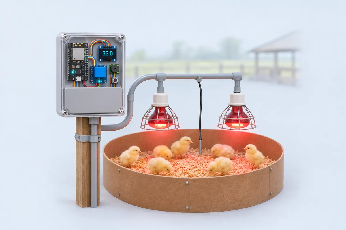
Board quirks: Two 100 W lamps draw under 1 A at 230 V — well inside a 10 A relay contact. For a bigger shed with 1–2 kW of heaters, the relay must switch a <strong>contactor coil</strong> instead, and the contactor switches the heaters. Either way the 230 V wiring, MCB, RCCB and earth are an electrician’s job. Hang the probe at <strong>chick height</strong> (5–8 cm above the litter) at the edge of the warm zone, not right under the lamp — that is the temperature the chicks feel. If the probe fails, the lamps switch <strong>off</strong> and the buzzer sounds. A lamp stuck on can overheat the chicks or set dry litter alight; a cold brooder gives you time to respond to the alarm. Press the button to step the chick age through weeks 1–5. It is stored in flash, so a power cut doesn’t reset it to week 1.
Code
// Poultry brooder temperature controller — ESP32 DevKit V1 + DS18B20 + OLED + relay + buzzer
// DS18B20 on D4 (4.7 kΩ pull-up to 3V3) hung at chick height. OLED on D21/D22.
// Relay module IN on D26 (active-LOW): COM/NO switch the brooder lamps (within the relay's rating).
// Push button D27 to GND: chick age in weeks (1-5), saved across power cuts. Buzzer module on D25.
// Target: 33 °C in week 1, 3 °C less each week, 21 °C from week 5.
#include <OneWire.h>
#include <DallasTemperature.h>
#include <Wire.h>
#include <Adafruit_GFX.h>
#include <Adafruit_SSD1306.h>
#include <Preferences.h>

constexpr uint8_t TEMP_PIN = 4;
constexpr uint8_t RELAY_PIN = 26;
constexpr uint8_t BUTTON_PIN = 27;
constexpr uint8_t BUZZER_PIN = 25;
constexpr bool RELAY_ACTIVE_LOW = true;
constexpr float HYST = 0.5;                       // lamps on below target-0.5, off above target+0.5
constexpr float ALARM_BAND = 4.0;                 // alarm when this far from the target...
constexpr uint32_t ALARM_AFTER_MS = 5UL * 60UL * 1000UL;  // ...for 5 minutes

OneWire bus(TEMP_PIN);
DallasTemperature probe(&bus);
Adafruit_SSD1306 oled(128, 64, &Wire, -1);
Preferences prefs;
uint8_t week = 1;
bool heater = false;
uint32_t outOfBandSince = 0;

float targetFor(uint8_t w) { return max(21.0f, 33.0f - 3.0f * (w - 1)); }

void setHeater(bool on) {
  heater = on;
  digitalWrite(RELAY_PIN, (on != RELAY_ACTIVE_LOW) ? HIGH : LOW);
}

void setup() {
  digitalWrite(RELAY_PIN, RELAY_ACTIVE_LOW ? HIGH : LOW);  // lamps off before the pin becomes an output
  pinMode(RELAY_PIN, OUTPUT);
  pinMode(BUTTON_PIN, INPUT_PULLUP);
  pinMode(BUZZER_PIN, OUTPUT);
  Serial.begin(115200);
  prefs.begin("brooder", false);
  week = constrain(prefs.getUChar("week", 1), 1, 5);
  probe.begin();
  Wire.begin(21, 22);
  if (!oled.begin(SSD1306_SWITCHCAPVCC, 0x3C)) Serial.println("OLED not found at 0x3C");
  oled.setTextColor(SSD1306_WHITE);
  Serial.printf("Brooder: week %u, target %.1f C\n", week, targetFor(week));
}

void loop() {
  if (digitalRead(BUTTON_PIN) == LOW) {
    week = week % 5 + 1;
    prefs.putUChar("week", week);
    Serial.printf("Week %u -> target %.1f C\n", week, targetFor(week));
    while (digitalRead(BUTTON_PIN) == LOW) delay(10);
  }

  probe.requestTemperatures();
  float t = probe.getTempCByIndex(0);
  float target = targetFor(week);
  bool probeOk = t > -50 && t < 85;  // -127 = no probe, 85 = a reset/glitch reading
  bool alarm;

  if (!probeOk) {
    setHeater(false);  // never run the lamps blind: they can overheat the chicks or start a fire
    alarm = true;
  } else {
    if (!heater && t < target - HYST) setHeater(true);
    if (heater && t > target + HYST) setHeater(false);
    if (fabs(t - target) > ALARM_BAND) {
      if (!outOfBandSince) outOfBandSince = millis();
    } else {
      outOfBandSince = 0;
    }
    alarm = outOfBandSince && millis() - outOfBandSince > ALARM_AFTER_MS;
  }
  digitalWrite(BUZZER_PIN, alarm ? HIGH : LOW);

  oled.clearDisplay();
  oled.setCursor(0, 0);
  oled.setTextSize(1);
  oled.printf("Week %u  set %.1f C\n", week, target);
  oled.setTextSize(3);
  if (probeOk) oled.printf("%.1f", t);
  else oled.print("--.-");
  oled.setTextSize(1);
  oled.setCursor(0, 44);
  oled.println(heater ? "LAMPS ON" : "lamps off");
  if (!probeOk) oled.print("PROBE FAULT!");
  else if (alarm) oled.print(t > target ? "TOO HOT!" : "TOO COLD!");
  oled.display();

  Serial.printf("t=%.1f target=%.1f heater=%d week=%u alarm=%d\n", t, target, heater, week, alarm);
  delay(2000);
}
// Poultry brooder temperature controller — ESP32 DevKit V1 + DS18B20 + OLED + relay + buzzer
// DS18B20 on D4 (4.7 kΩ pull-up to 3V3) hung at chick height. OLED on D21/D22.
// Relay module IN on D26 (active-LOW): COM/NO switch the brooder lamps (within the relay's rating).
// Push button D27 to GND: chick age in weeks (1-5), saved across power cuts. Buzzer module on D25.
// Target: 33 °C in week 1, 3 °C less each week, 21 °C from week 5.
#include <OneWire.h>
#include <DallasTemperature.h>
#include <Wire.h>
#include <Adafruit_GFX.h>
#include <Adafruit_SSD1306.h>
#include <Preferences.h>
constexpr uint8_t TEMP_PIN = 4;
constexpr uint8_t RELAY_PIN = 26;
constexpr uint8_t BUTTON_PIN = 27;
constexpr uint8_t BUZZER_PIN = 25;
constexpr bool RELAY_ACTIVE_LOW = true;
constexpr float HYST = 0.5; // lamps on below target-0.5, off above target+0.5
constexpr float ALARM_BAND = 4.0; // alarm when this far from the target...
constexpr uint32_t ALARM_AFTER_MS = 5UL * 60UL * 1000UL; // ...for 5 minutes
OneWire bus(TEMP_PIN);
DallasTemperature probe(&bus);
Adafruit_SSD1306 oled(128, 64, &Wire, -1);
Preferences prefs;
uint8_t week = 1;
bool heater = false;
uint32_t outOfBandSince = 0;
float targetFor(uint8_t w) { return max(21.0f, 33.0f - 3.0f * (w - 1)); }
void setHeater(bool on) {
heater = on;
digitalWrite(RELAY_PIN, (on != RELAY_ACTIVE_LOW) ? HIGH : LOW);
}
void setup() {
digitalWrite(RELAY_PIN, RELAY_ACTIVE_LOW ? HIGH : LOW); // lamps off before the pin becomes an output
pinMode(RELAY_PIN, OUTPUT);
pinMode(BUTTON_PIN, INPUT_PULLUP);
pinMode(BUZZER_PIN, OUTPUT);
Serial.begin(115200);
prefs.begin("brooder", false);
week = constrain(prefs.getUChar("week", 1), 1, 5);
probe.begin();
Wire.begin(21, 22);
if (!oled.begin(SSD1306_SWITCHCAPVCC, 0x3C)) Serial.println("OLED not found at 0x3C");
oled.setTextColor(SSD1306_WHITE);
Serial.printf("Brooder: week %u, target %.1f C\n", week, targetFor(week));
}
void loop() {
if (digitalRead(BUTTON_PIN) == LOW) {
week = week % 5 + 1;
prefs.putUChar("week", week);
Serial.printf("Week %u -> target %.1f C\n", week, targetFor(week));
while (digitalRead(BUTTON_PIN) == LOW) delay(10);
}
probe.requestTemperatures();
float t = probe.getTempCByIndex(0);
float target = targetFor(week);
bool probeOk = t > -50 && t < 85; // -127 = no probe, 85 = a reset/glitch reading
bool alarm;
if (!probeOk) {
setHeater(false); // never run the lamps blind: they can overheat the chicks or start a fire
alarm = true;
} else {
if (!heater && t < target - HYST) setHeater(true);
if (heater && t > target + HYST) setHeater(false);
if (fabs(t - target) > ALARM_BAND) {
if (!outOfBandSince) outOfBandSince = millis();
} else {
outOfBandSince = 0;
}
alarm = outOfBandSince && millis() - outOfBandSince > ALARM_AFTER_MS;
}
digitalWrite(BUZZER_PIN, alarm ? HIGH : LOW);
oled.clearDisplay();
oled.setCursor(0, 0);
oled.setTextSize(1);
oled.printf("Week %u set %.1f C\n", week, target);
oled.setTextSize(3);
if (probeOk) oled.printf("%.1f", t);
else oled.print("--.-");
oled.setTextSize(1);
oled.setCursor(0, 44);
oled.println(heater ? "LAMPS ON" : "lamps off");
if (!probeOk) oled.print("PROBE FAULT!");
else if (alarm) oled.print(t > target ? "TOO HOT!" : "TOO COLD!");
oled.display();
Serial.printf("t=%.1f target=%.1f heater=%d week=%u alarm=%d\n", t, target, heater, week, alarm);
delay(2000);
}Compiled for esp32 on esp32 3.3.12 with OneWire 2.3.8 · 3 Nov 2026
How it works
Day-old chicks can’t keep themselves warm for their first weeks. Too cold and they huddle, stop eating and die; too hot and they pant and dehydrate. Small poultry farmers across India brood batches of 100–500 chicks under bulbs and adjust them by guesswork — and a cold night or a hot afternoon can cost a large part of a batch.
How it works
A DS18B20 waterproof probe hangs at chick height. Every 2 seconds the ESP32 reads it and compares it with the target for the chicks’ age: 33 °C in week 1, then 3 °C less each week, and 21 °C from week 5. You set the week with the push button.
The relay switches the brooder lamps with ±0.5 °C hysteresis: on below target − 0.5 °C, off above target + 0.5 °C. That stops the relay chattering when the temperature sits right on the line.
If the temperature stays more than 4 °C away from the target for 5 minutes, the buzzer sounds and the OLED says TOO HOT or TOO COLD. A missing or faulty probe (it reads −127 °C or the 85 °C power-on value) turns the lamps off and sounds the buzzer at once.
Why these parts
- DS18B20 probe — waterproof, digital (no calibration drift on a long cable), and accurate to ±0.5 °C.
- Relay within rating — 200 W of lamps is about 0.9 A. Check your relay module’s contact rating printed on the blue relay (10 A 250 V AC is common).
- ESP32 — stores the week in flash and leaves room for a phone alert later.
Calibration
Put the probe next to a good thermometer in a glass of water at room temperature; they should agree within 0.5 °C. Then watch the chicks for the first day — the temperature table is a starting point, and every breed and shed is a bit different.
India notes
North Indian winter nights fall below 5 °C and summer afternoons above 40 °C — in summer the controller may keep the lamps off all day and you’ll need shade and ventilation instead. Use an RCCB on the brooder circuit: sheds are damp, and lamp holders get splashed when drinkers are refilled.
Troubleshooting
The OLED shows --.- and PROBE FAULT
The DS18B20 doesn’t answer. Check the 4.7 kΩ pull-up between DQ and 3V3 and the three probe wires (red VDD, black GND, yellow DQ). Long probe leads (over 5 m) need a lower pull-up, around 2.2 kΩ.
The lamps switch on and off every few seconds
The probe is too close to a lamp, so it heats and cools faster than the brooder air. Move it to the edge of the warm zone, or raise HYST to 1.0 °C.
The chicks crowd under the lamp even at the set temperature
Watch the chicks, not just the number: crowding means cold, spreading to the walls and panting means hot. Draughts at chick level make them feel colder — raise the brooder guard.
Upgrades
- Send a phone alert through ntfy.sh on an alarm — useful at night.
- Add a DHT22 to watch humidity and ammonia-wet litter, and an exhaust fan through a contactor.
- Use a dimmer-friendly heater with an SSR and PID control for a steadier temperature.