Parts list
| Part | Qty | Approx. | Buy |
|---|---|---|---|
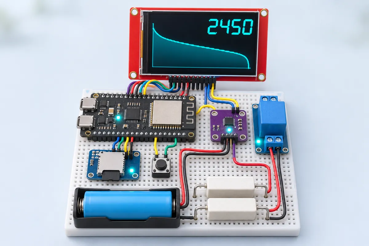
| ESP32-S3-DevKitC-1 | 1 | ₹750 | Buy ESP32-S3-DevKitC-1 |
| INA219 current sensor module (0.1 Ω shunt) | 1 | ₹180 | Buy INA219 current sensor module (0.1 Ω shunt) |
| 2.8" ILI9341 SPI TFT (320×240) | 1 | ₹650 | Buy 2.8" ILI9341 SPI TFT (320×240) |
| microSD card module (5 V, with regulator) + 8 GB card | 1 | ₹300 | Buy microSD card module (5 V, with regulator) + 8 GB card |
| 1-channel 5 V relay module (3.3 V trigger) | 1 | ₹70 | Buy 1-channel 5 V relay module (3.3 V trigger) |
| 10 Ω 5 W cement resistor | 2 | ₹30 | Buy 10 Ω 5 W cement resistor |
| 18650 single-cell holder with leads | 1 | ₹40 | Buy 18650 single-cell holder with leads |
| 12 mm push button | 1 | ₹10 | Buy 12 mm push button |
| Breadboard + jumper wires + 0.75 mm² wire for the load loop | 1 | ₹120 | Buy Breadboard + jumper wires + 0.75 mm² wire for the load loop |
| Total | ₹2,150 |
Affiliate disclosure: “Buy” links may earn FlashReady a small commission at no extra cost to you. Prices are indicative.
Wiring
| ESP32-S3-DevKitC-1 | Part · pin | Wire | Notes |
|---|---|---|---|
| — | 1-channel relay module (5 V coil) · NO | — | To Load: 2× 10 Ω 5 W in parallel (+) (not drawn) |
| 8 | INA219 DC current/voltage sensor · SDA | blue | GPIO8 — default I2C SDA |
| 9 | INA219 DC current/voltage sensor · SCL | yellow | GPIO9 — default I2C SCL |
| 3V3 | INA219 DC current/voltage sensor · VCC | red | |
| GND | INA219 DC current/voltage sensor · GND | black | Common ground: board, INA219, cell − and the far end of the load resistors |
| 18650 cell under test (in a holder) · + | INA219 DC current/voltage sensor · VIN+ | red | Thick wire (0.75 mm² or more) — up to about 0.85 A flows here |
| 18650 cell under test (in a holder) · - | INA219 DC current/voltage sensor · GND | black | Cell − also takes the other end of the load resistors |
| 7 | 1-channel relay module (5 V coil) · IN | orange | Active-LOW: LOW = load connected. Pick a module rated for a 3.3 V trigger |
| 5V | 1-channel relay module (5 V coil) · DC+ | red | |
| GND | 1-channel relay module (5 V coil) · DC− | black | |
| — | INA219 DC current/voltage sensor · VIN- → 1-channel relay module (5 V coil) · COM | red | Load path: cell + → shunt → VIN− → relay COM → NO → load resistors → cell −. Same thick wire |
| 5V | ILI9341 TFT 2.4″ / 2.8″ (240×320, SPI, touch) · VCC | red | 5 V with jumper J1 open (the TFT has its own 3.3 V regulator) |
| GND | ILI9341 TFT 2.4″ / 2.8″ (240×320, SPI, touch) · GND | black | |
| 10 | ILI9341 TFT 2.4″ / 2.8″ (240×320, SPI, touch) · CS | white | |
| 5 | ILI9341 TFT 2.4″ / 2.8″ (240×320, SPI, touch) · RESET | brown | |
| 4 | ILI9341 TFT 2.4″ / 2.8″ (240×320, SPI, touch) · DC | purple | |
| 11 | ILI9341 TFT 2.4″ / 2.8″ (240×320, SPI, touch) · SDI(MOSI) | green | GPIO11 — FSPI MOSI, shared with the SD card |
| 12 | ILI9341 TFT 2.4″ / 2.8″ (240×320, SPI, touch) · SCK | yellow | GPIO12 — FSPI SCK, shared with the SD card |
| 3V3 | ILI9341 TFT 2.4″ / 2.8″ (240×320, SPI, touch) · LED | red | Backlight always on. Leave SDO(MISO) unconnected so it can’t fight the SD card |
| 5V | MicroSD card module (SPI) · VCC | red | The common module needs 5 V for its regulator |
| GND | MicroSD card module (SPI) · GND | black | |
| 13 | MicroSD card module (SPI) · MISO | blue | GPIO13 — FSPI MISO (only the SD card drives it) |
| 11 | MicroSD card module (SPI) · MOSI | green | |
| 12 | MicroSD card module (SPI) · SCK | yellow | |
| 6 | MicroSD card module (SPI) · CS | cyan | |
| 2 | Push button (6 mm tactile switch) · 1 | green | START / STOP — GPIO2 with INPUT_PULLUP |
| GND | Push button (6 mm tactile switch) · 2 | black |
Board quirks: The two 10 Ω resistors in parallel make 5 Ω: about 0.84 A at 4.2 V and 0.6 A near the end. They get <strong>hot</strong> (about 3.5 W) — mount them in free air on a metal plate, never touching the breadboard or wires. The INA219 reads the voltage at its VIN− terminal, under load. The sketch stops at 3.00 V under load (three readings in a row), which leaves a healthy margin above the 2.5–2.75 V floor of most cells. Never test a cell that starts below 3.3 V — it is either flat or damaged. Internal resistance is measured once at the start (open voltage minus loaded voltage, divided by the current). It includes the holder springs and wires, so compare cells in the same holder rather than with datasheet figures. The TFT’s SDO(MISO) is left unconnected on purpose: many ILI9341 boards never release MISO, which corrupts SD card reads on the shared bus. Upload and Serial use the DevKitC’s <strong>UART</strong> port. The relay module, TFT and SD card all hang off the 5V pin, so power the board from a USB port that gives at least 500 mA.
Code
// 18650 capacity tester — ESP32-S3-DevKitC-1 + INA219 + 2.8" ILI9341 + microSD + relay.
// The cell discharges through a 5 ohm / 10 W load while the INA219 measures volts and amps.
// The S3 adds up mAh and mWh every second, draws the discharge curve on the TFT, logs a CSV
// to the microSD card and opens the relay at 3.00 V so the cell is never over-discharged.
// Wiring: INA219 SDA 8 / SCL 9 (default Wire), VIN+ from cell +, VIN- to relay COM.
// SPI (FSPI defaults): SCK 12, MOSI 11, MISO 13 (SD card only). TFT CS 10, DC 4, RESET 5.
// SD CS 6. Relay IN 7 (active-LOW). Start button GPIO2 to GND.
#include <Wire.h>
#include <SPI.h>
#include <SD.h>
#include <Adafruit_INA219.h>
#include <Adafruit_GFX.h>
#include <Adafruit_ILI9341.h>

constexpr int TFT_CS = 10, TFT_DC = 4, TFT_RST = 5, SD_CS = 6, RELAY = 7, BTN = 2;
constexpr float CUTOFF_V = 3.00;  // stop here (under load); 2.75 V is the absolute floor for most cells
constexpr float MIN_START_V = 3.30;

Adafruit_INA219 ina;
Adafruit_ILI9341 tft(TFT_CS, TFT_DC, TFT_RST);
enum State { IDLE, RUNNING, DONE } state = IDLE;
bool sdOk = false;
File logFile;
uint32_t startMs = 0, lastSample = 0;
double mAh = 0, mWh = 0;
float vOpen = 0, rInt = 0;
int lastX = -1, lastY = -1;

void relay(bool on) { digitalWrite(RELAY, on ? LOW : HIGH); }  // active-LOW module

void header(const char* msg, uint16_t col) {
  tft.fillRect(0, 0, 320, 24, col);
  tft.setTextColor(ILI9341_BLACK);
  tft.setTextSize(2);
  tft.setCursor(6, 4);
  tft.print(msg);
}

void axes() {
  tft.fillRect(0, 120, 320, 120, ILI9341_BLACK);
  tft.drawRect(30, 124, 286, 110, ILI9341_DARKGREY);
  tft.setTextSize(1);
  tft.setTextColor(ILI9341_DARKGREY);
  tft.setCursor(0, 124);
  tft.print("4.2V");
  tft.setCursor(0, 226);
  tft.print("3.0V");
  lastX = lastY = -1;
}

void numbers(float v, float mA, uint32_t secs) {
  tft.fillRect(0, 28, 320, 90, ILI9341_BLACK);
  tft.setTextColor(ILI9341_WHITE);
  tft.setTextSize(3);
  tft.setCursor(6, 32);
  tft.printf("%.3f V", v);
  tft.setCursor(170, 32);
  tft.printf("%4.0fmA", mA);
  tft.setTextColor(ILI9341_GREEN);
  tft.setCursor(6, 64);
  tft.printf("%.0f mAh", mAh);
  tft.setTextSize(2);
  tft.setTextColor(ILI9341_LIGHTGREY);
  tft.setCursor(6, 96);
  tft.printf("%.2f Wh  %02lu:%02lu:%02lu  R %.0fmO", mWh / 1000.0, secs / 3600, secs / 60 % 60, secs % 60, rInt * 1000);
}

// One point per minute; the x axis covers 286 minutes (enough for a 3000 mAh cell at 0.7 A).
void plot(float v, uint32_t secs) {
  int x = 31 + min<uint32_t>(secs / 60, 284);
  int y = 232 - (int)((constrain(v, 3.0f, 4.2f) - 3.0f) / 1.2f * 106);
  if (lastX >= 0) tft.drawLine(lastX, lastY, x, y, ILI9341_YELLOW);
  lastX = x;
  lastY = y;
}

void startTest() {
  vOpen = ina.getBusVoltage_V();
  if (vOpen < MIN_START_V) {
    header("Cell too low / missing", ILI9341_ORANGE);
    Serial.printf("Not starting: %.2f V (need %.2f V)\n", vOpen, MIN_START_V);
    return;
  }
  relay(true);
  delay(2000);  // let the voltage settle under load
  float vLoad = ina.getBusVoltage_V();
  float a = ina.getCurrent_mA() / 1000.0;
  rInt = a > 0.05 ? (vOpen - vLoad) / a : 0;  // includes holder and wire resistance
  mAh = mWh = 0;
  startMs = lastSample = millis();
  if (sdOk) {
    char name[24];
    for (int i = 1; i < 1000; i++) {
      snprintf(name, sizeof name, "/cell_%03d.csv", i);
      if (!SD.exists(name)) break;
    }
    logFile = SD.open(name, FILE_WRITE);
    if (logFile) logFile.printf("# open %.3f V, internal %.0f mOhm\nseconds,volts,mA,mAh\n", vOpen, rInt * 1000);
    Serial.printf("Logging to %s\n", name);
  }
  state = RUNNING;
  header("Discharging...", ILI9341_CYAN);
  axes();
  Serial.printf("Start: open %.3f V, loaded %.3f V, %.0f mA, R %.0f mOhm\n", vOpen, vLoad, a * 1000, rInt * 1000);
  Serial.println("seconds,volts,mA,mAh");
}

void setup() {
  Serial.begin(115200);
  pinMode(RELAY, OUTPUT);
  relay(false);
  pinMode(BTN, INPUT_PULLUP);
  Wire.begin(8, 9);
  if (!ina.begin()) Serial.println("INA219 not found at 0x40 - check SDA 8 / SCL 9");
  ina.setCalibration_32V_2A();
  SPI.begin(12, 13, 11);
  tft.begin(40000000);
  tft.setRotation(1);
  tft.fillScreen(ILI9341_BLACK);
  sdOk = SD.begin(SD_CS, SPI, 20000000);
  if (!sdOk) Serial.println("No microSD card - testing without a log file");
  header("Insert cell, press START", ILI9341_WHITE);
  axes();
}

void loop() {
  static bool lastBtn = HIGH;
  bool b = digitalRead(BTN);
  if (b == LOW && lastBtn == HIGH) {
    delay(30);
    if (state == RUNNING) {  // a second press stops the test early
      relay(false);
      state = DONE;
      header("Stopped by button", ILI9341_ORANGE);
      if (logFile) logFile.close();
    } else startTest();
  }
  lastBtn = b;

  if (millis() - lastSample < 1000) return;
  uint32_t dt = millis() - lastSample;
  lastSample = millis();
  float v = ina.getBusVoltage_V();
  float mA = state == RUNNING ? ina.getCurrent_mA() : 0;
  uint32_t secs = state == IDLE ? 0 : (lastSample - startMs) / 1000;
  if (state == RUNNING) {
    mAh += mA * dt / 3600000.0;
    mWh += mA * v * dt / 3600000.0;
    Serial.printf("%lu,%.3f,%.0f,%.1f\n", secs, v, mA, mAh);
    if (logFile && secs % 10 == 0) {
      logFile.printf("%lu,%.3f,%.0f,%.1f\n", secs, v, mA, mAh);
      logFile.flush();
    }
    if (secs % 60 == 0) plot(v, secs);
    static uint8_t low = 0;
    low = v < CUTOFF_V ? low + 1 : 0;
    if (low >= 3) {  // three readings in a row, so one noisy sample doesn't end the test
      relay(false);
      state = DONE;
      header("Done - cell rested", ILI9341_GREEN);
      if (logFile) {
        logFile.printf("# capacity %.0f mAh, %.2f Wh\n", mAh, mWh / 1000.0);
        logFile.close();
      }
      Serial.printf("Cut-off at %.3f V: %.0f mAh, %.2f Wh in %lu s\n", v, mAh, mWh / 1000.0, secs);
    }
  }
  if (state != DONE) numbers(v, mA, secs);
}
// 18650 capacity tester — ESP32-S3-DevKitC-1 + INA219 + 2.8" ILI9341 + microSD + relay.
// The cell discharges through a 5 ohm / 10 W load while the INA219 measures volts and amps.
// The S3 adds up mAh and mWh every second, draws the discharge curve on the TFT, logs a CSV
// to the microSD card and opens the relay at 3.00 V so the cell is never over-discharged.
// Wiring: INA219 SDA 8 / SCL 9 (default Wire), VIN+ from cell +, VIN- to relay COM.
// SPI (FSPI defaults): SCK 12, MOSI 11, MISO 13 (SD card only). TFT CS 10, DC 4, RESET 5.
// SD CS 6. Relay IN 7 (active-LOW). Start button GPIO2 to GND.
#include <Wire.h>
#include <SPI.h>
#include <SD.h>
#include <Adafruit_INA219.h>
#include <Adafruit_GFX.h>
#include <Adafruit_ILI9341.h>
constexpr int TFT_CS = 10, TFT_DC = 4, TFT_RST = 5, SD_CS = 6, RELAY = 7, BTN = 2;
constexpr float CUTOFF_V = 3.00; // stop here (under load); 2.75 V is the absolute floor for most cells
constexpr float MIN_START_V = 3.30;
Adafruit_INA219 ina;
Adafruit_ILI9341 tft(TFT_CS, TFT_DC, TFT_RST);
enum State { IDLE, RUNNING, DONE } state = IDLE;
bool sdOk = false;
File logFile;
uint32_t startMs = 0, lastSample = 0;
double mAh = 0, mWh = 0;
float vOpen = 0, rInt = 0;
int lastX = -1, lastY = -1;
void relay(bool on) { digitalWrite(RELAY, on ? LOW : HIGH); } // active-LOW module
void header(const char* msg, uint16_t col) {
tft.fillRect(0, 0, 320, 24, col);
tft.setTextColor(ILI9341_BLACK);
tft.setTextSize(2);
tft.setCursor(6, 4);
tft.print(msg);
}
void axes() {
tft.fillRect(0, 120, 320, 120, ILI9341_BLACK);
tft.drawRect(30, 124, 286, 110, ILI9341_DARKGREY);
tft.setTextSize(1);
tft.setTextColor(ILI9341_DARKGREY);
tft.setCursor(0, 124);
tft.print("4.2V");
tft.setCursor(0, 226);
tft.print("3.0V");
lastX = lastY = -1;
}
void numbers(float v, float mA, uint32_t secs) {
tft.fillRect(0, 28, 320, 90, ILI9341_BLACK);
tft.setTextColor(ILI9341_WHITE);
tft.setTextSize(3);
tft.setCursor(6, 32);
tft.printf("%.3f V", v);
tft.setCursor(170, 32);
tft.printf("%4.0fmA", mA);
tft.setTextColor(ILI9341_GREEN);
tft.setCursor(6, 64);
tft.printf("%.0f mAh", mAh);
tft.setTextSize(2);
tft.setTextColor(ILI9341_LIGHTGREY);
tft.setCursor(6, 96);
tft.printf("%.2f Wh %02lu:%02lu:%02lu R %.0fmO", mWh / 1000.0, secs / 3600, secs / 60 % 60, secs % 60, rInt * 1000);
}
// One point per minute; the x axis covers 286 minutes (enough for a 3000 mAh cell at 0.7 A).
void plot(float v, uint32_t secs) {
int x = 31 + min<uint32_t>(secs / 60, 284);
int y = 232 - (int)((constrain(v, 3.0f, 4.2f) - 3.0f) / 1.2f * 106);
if (lastX >= 0) tft.drawLine(lastX, lastY, x, y, ILI9341_YELLOW);
lastX = x;
lastY = y;
}
void startTest() {
vOpen = ina.getBusVoltage_V();
if (vOpen < MIN_START_V) {
header("Cell too low / missing", ILI9341_ORANGE);
Serial.printf("Not starting: %.2f V (need %.2f V)\n", vOpen, MIN_START_V);
return;
}
relay(true);
delay(2000); // let the voltage settle under load
float vLoad = ina.getBusVoltage_V();
float a = ina.getCurrent_mA() / 1000.0;
rInt = a > 0.05 ? (vOpen - vLoad) / a : 0; // includes holder and wire resistance
mAh = mWh = 0;
startMs = lastSample = millis();
if (sdOk) {
char name[24];
for (int i = 1; i < 1000; i++) {
snprintf(name, sizeof name, "/cell_%03d.csv", i);
if (!SD.exists(name)) break;
}
logFile = SD.open(name, FILE_WRITE);
if (logFile) logFile.printf("# open %.3f V, internal %.0f mOhm\nseconds,volts,mA,mAh\n", vOpen, rInt * 1000);
Serial.printf("Logging to %s\n", name);
}
state = RUNNING;
header("Discharging...", ILI9341_CYAN);
axes();
Serial.printf("Start: open %.3f V, loaded %.3f V, %.0f mA, R %.0f mOhm\n", vOpen, vLoad, a * 1000, rInt * 1000);
Serial.println("seconds,volts,mA,mAh");
}
void setup() {
Serial.begin(115200);
pinMode(RELAY, OUTPUT);
relay(false);
pinMode(BTN, INPUT_PULLUP);
Wire.begin(8, 9);
if (!ina.begin()) Serial.println("INA219 not found at 0x40 - check SDA 8 / SCL 9");
ina.setCalibration_32V_2A();
SPI.begin(12, 13, 11);
tft.begin(40000000);
tft.setRotation(1);
tft.fillScreen(ILI9341_BLACK);
sdOk = SD.begin(SD_CS, SPI, 20000000);
if (!sdOk) Serial.println("No microSD card - testing without a log file");
header("Insert cell, press START", ILI9341_WHITE);
axes();
}
void loop() {
static bool lastBtn = HIGH;
bool b = digitalRead(BTN);
if (b == LOW && lastBtn == HIGH) {
delay(30);
if (state == RUNNING) { // a second press stops the test early
relay(false);
state = DONE;
header("Stopped by button", ILI9341_ORANGE);
if (logFile) logFile.close();
} else startTest();
}
lastBtn = b;
if (millis() - lastSample < 1000) return;
uint32_t dt = millis() - lastSample;
lastSample = millis();
float v = ina.getBusVoltage_V();
float mA = state == RUNNING ? ina.getCurrent_mA() : 0;
uint32_t secs = state == IDLE ? 0 : (lastSample - startMs) / 1000;
if (state == RUNNING) {
mAh += mA * dt / 3600000.0;
mWh += mA * v * dt / 3600000.0;
Serial.printf("%lu,%.3f,%.0f,%.1f\n", secs, v, mA, mAh);
if (logFile && secs % 10 == 0) {
logFile.printf("%lu,%.3f,%.0f,%.1f\n", secs, v, mA, mAh);
logFile.flush();
}
if (secs % 60 == 0) plot(v, secs);
static uint8_t low = 0;
low = v < CUTOFF_V ? low + 1 : 0;
if (low >= 3) { // three readings in a row, so one noisy sample doesn't end the test
relay(false);
state = DONE;
header("Done - cell rested", ILI9341_GREEN);
if (logFile) {
logFile.printf("# capacity %.0f mAh, %.2f Wh\n", mAh, mWh / 1000.0);
logFile.close();
}
Serial.printf("Cut-off at %.3f V: %.0f mAh, %.2f Wh in %lu s\n", v, mAh, mWh / 1000.0, secs);
}
}
if (state != DONE) numbers(v, mA, secs);
}Compiled for s3devkitc on esp32 3.3.12 with Adafruit INA219 1.2.3 · 3 Nov 2026
How it works
Laptop packs and power banks thrown out in India are full of 18650 cells, and electronics markets sell them “tested” by the kilo. Some are excellent; many have lost half their capacity, and new cells online often carry fake “9900 mAh” labels. The only honest test is to empty a fully charged cell through a known load and count the charge that comes out. This tester does that and keeps a record.
Charge the cell fully (a TP4056 is fine), put it in the holder and press START. The ESP32-S3 first reads the open-circuit voltage, closes the relay, waits two seconds and reads the voltage again under load — the drop divided by the current is the cell’s internal resistance, a good sign of age. Then, once a second, it reads volts and milliamps from the INA219, adds mA × time to a running mAh total and mA × V × time to mWh.
The 2.8″ ILI9341 shows the live numbers in large digits and draws the discharge curve, one point a minute: a healthy cell holds a long flat plateau around 3.6–3.7 V, a tired one falls away early. Every ten seconds a line goes into cell_001.csv, cell_002.csv… on the microSD card, with the open voltage and internal resistance at the top, ready for a spreadsheet. When the voltage stays below 3.00 V for three readings, the relay opens and the final capacity stays on screen.
The S3 drives the TFT and the SD card on one fast SPI bus (its FSPI defaults GPIO11/12/13), and the INA219 sits on the default I2C pins 8 and 9, so no pin needs remapping. Both strapping pins (GPIO0 and 46) and the USB lines stay untouched.
Troubleshooting
“Cell too low / missing” with a good cell
The INA219 sees no voltage on VIN−. The relay is open at that moment, so VIN− only reaches the cell through the INA219’s 0.1 Ω shunt — check VIN+ goes to the cell + and that cell − is wired to GND.
Current reads 0 mA while discharging
The relay isn’t closing (listen for the click) or the load loop is open. Some relay modules don’t switch from a 3.3 V signal; use one sold for ESP32 / 3.3 V.
The SD log is empty or the card isn’t found
Format the card as FAT32, check CS on GPIO6 and that the module has 5 V. If the TFT’s MISO pin is wired, disconnect it.
Capacity is far below the label
Many “9900 mAh” cells sold online are rewrapped old cells — 600–1500 mAh is common. A genuine new 18650 usually gives 2000–3400 mAh.
Upgrades
- Replace the relay with a logic-level MOSFET and PWM it for a constant-current load.
- Add a TP4056 charger stage so the tester charges, rests and discharges each cell automatically.
- Test four cells in parallel slots with four INA219s at addresses 0x40, 0x41, 0x44 and 0x45.